Posts

Showing posts from March, 2021

WEEK 9: (FYP2) UPLOAD AND TESTING THE CODING ON THE CIRCUIT

Image
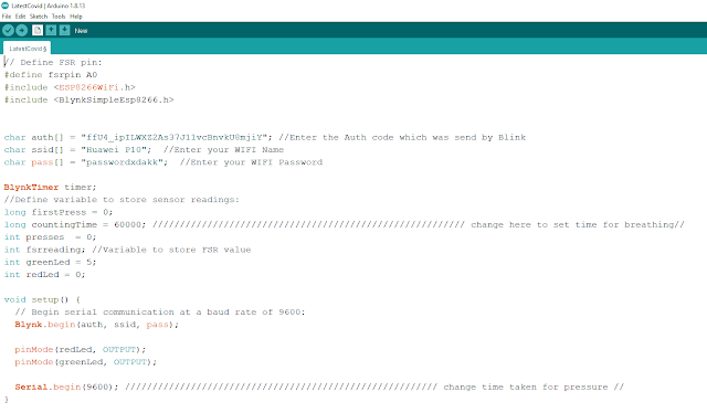
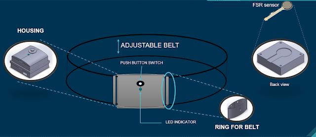
This is week 9. For this week I will try upload the source code in the NodeMCU the test the circuit functionility.   In this system, the NodeMCU is connected to the internet and through the Blynk server to display the data retrieve from the FSR sensor. This is an excellent example of an IoT application in which the PUI can be monitored remotely using internet connections. Below is the coding upload in the NodeMCU. When the circuit connected to the Blynk via Wi-Fi the Green LED will light up. When the Force Sencitivity Resistor is press and release the Red LED and Green LED will light up respectively.

WEEK 8 : (FYP2)THESIS WORKSHOP & SETUP BLYNK APPLICATION CONNECTION

Image
In this week, the briefing was conducted online via M. Teams as usuall, all the attandance of all FYP 2 student is compulsory. The briefing was by Sir Osman and En Ahmad Syukri. This week briefing is about the  Discussion  (Chapter 4) and Conclusion (Chapter 5).                     Date: 24/3/2021                     Venue: Online via M.Teams                     Time: 3:00PM - 5:00PM In this briefing, the FYP committees have been brief us about: How to write the Discussion and Conclusion If possible do a graph, chart or table for the measurement result           *if graph, it must has a title, the x and y axis must be correct The discussion and conclusion must be in past tense The picture of the result must has a caption For conclusion, just summarize what has been done Its okay if the project not function but must explain the reason why doesn't function The conclusion must reflect back the objective Other activity im doing for this week is to setup blynk application for the projec

WEEK 7 : (FYP2)TEST THE SENSOR OF CIRCUIT ON THE BREADBOARD

Image
After doing the schematic diagram of the circuit last week, so its time to test the circuit connection on the breadboard. So here is the circuit I construct to test the functionality and the connection of the circuit. The picture above show that the circuit work after it was power up by 3.7 Volt Lithium ion battery. The test pen and multimeter is use to check the connection between the components.  

WEEK 6 : (FYP2) DESIGN SCHEMATIC DIAGRAM OF THE CIRCUIT

Image
 For this week, I'm going to design the circuit diagram for my project. This circuit consist of several component including the microcontroller NodeMCU.   So, I'm using the fritzing software to design the circuit diagram on breadboard. I'm using A0 as the Input for the Force Sensitivity Resistor. For LED I'm using the D1 and D3 pin for the output. The push button is use as the external reset button and is connected to the RESET pin. The switch is use to turn on and off the circuit. So how this device work. when we are breathing, there will be a change in resistance with respect to the force of the thoracic. When breathing occurs, there will be increase in the force. This increase in force will reduce the resistance in FSR and this reduction in resistance will allow conductance and this conduction is counted as one breath. This is the process involved in measuring the heart rate.

WEEK 5 : (FYP2) PROJECT DESIGN

Image
 For this week, I'm using the paint sofware and the microsoft word to design the project.